This post was translated from the original with AI assistance. Read the original
The TCP/IP Protocol Suite#
TCP/IP is a protocol suite that implements the Internet architecture; it originates from the ARPANET reference model.
Protocol Suite#
A collection of related protocols is called a protocol suite.
Architecture / Reference Model#
The design that specifies the relationships among the various protocols in a protocol suite and divides up the tasks that need to be accomplished is called the suite’s architecture or reference model.
Principles of the Internet Architecture#
The Internet architecture should interconnect multiple networks and run multiple applications simultaneously across the interconnected networks.
The Internet Goals List#
- Internet communication must continue when networks or gateways fail.
- The Internet must support multiple types of communication services.
- The Internet architecture must accommodate a variety of networks.
- The Internet architecture must permit distributed management of its resources.
- The Internet architecture must be cost-effective.
- The Internet architecture must permit the connection of low-capability hosts.
- The resources used in the Internet must be accountable.
Key Approaches and Results#
Packets, Connections, and Datagrams#
Telephone Networks#
Up until the 1960s, the primary concept of networking was based on the telephone network. The telephone network is a form of network transmission that establishes a connection (originally a physical circuit) between the two parties of a call, provides the user with a certain amount of bandwidth or capacity, and thereby transmits information. It went through a development process from analog networks to digital networks, ultimately guaranteeing a certain level of reliability and performance. However, using a telephone network means that during a call you pay for it even when you aren’t transmitting any data.
The Idea of Packet Switching#
An important concept that emerged in the 1960s was the idea of packet switching.
The Packet-Switching Concept
A packet is a block of digital information containing a certain number of bytes. Packets from different sources or senders can be combined and later split apart, which is called multiplexing. On their way to their destination, packets are transmitted between switching devices, and the path can change.
Advantages of Packet Switching
- The network is more resilient, so there’s no need to worry about the network being physically attacked
- Statistical multiplexing allows better use of network links and switching devices
How Packets Are Scheduled
When a packet switch receives a packet, the packet is usually stored in a buffer or queue and scheduled for processing in first-in, first-out (FIFO) order.
Statistical Multiplexing
Statistical multiplexing is the primary method used in the Internet to handle mixed traffic from different sources; it’s implemented based on FIFO buffer management and on-demand scheduling.
Advantage
High utilization: if the network bandwidth is being used and there’s traffic flowing through it, then every bottleneck or congestion point in the network will be busy (this isn’t a downside; being busy means high utilization).
Disadvantage
Limited predictability: packets ultimately end up scattered all over the place, and a contraction at any point can make a line busy.
Time-Division Multiplexing and Static Multiplexing
Time-division multiplexing and static multiplexing usually reserve a certain amount of time or other resources for data on each connection, giving better predictability but failing to fully utilize the network bandwidth. They were ultimately replaced by Digital Subscriber Line (DSL) technology and cable modems that support Internet connectivity.
Connection-Oriented#
A connection-oriented approach requires storing some information or state for each connection in each switch. Before a signaling protocol is used, the state for each flow has already been established; this protocol supports connection setup, teardown, and state information.
Datagrams#
A datagram is a specific type of packet in which all the identifying information about the source and final destination is contained within the packet (rather than in the packet switches). Although this usually requires larger packets, it doesn’t require maintaining connection state in the switches; it can be used to build a connectionless network, and there’s no need to use a complex signaling protocol.
Message Boundaries / Record Markers#
When a block of information is sent into the network, these blocks may or may not be preserved by the communication protocol. Most datagram protocols preserve message boundaries.
TCP does not preserve message boundaries.
The End-to-End Argument and Fate Sharing#
The End-to-End Argument#
“The function in question can completely and correctly be implemented only with the knowledge and help of the application standing at the endpoints of the communication system. Therefore, providing that questioned function as a feature of the communication system itself is not possible.”
// TODO add content
Fate Sharing#
// TODO add content
Error Control and Flow Control#
Error Control#
Data corruption or loss can occur in a network. This can happen for various reasons, such as hardware problems, modification during transmission, going out of range on a wireless network, and other factors. Handling such errors is called error control.
Design and Implementation#
Layering#
The concept of layering is based on a model called the Open Systems Interconnection standard (OSI), which was defined by the International Organization for Standardization (ISO).
The OSI Seven-Layer Network Model Defined by ISO#
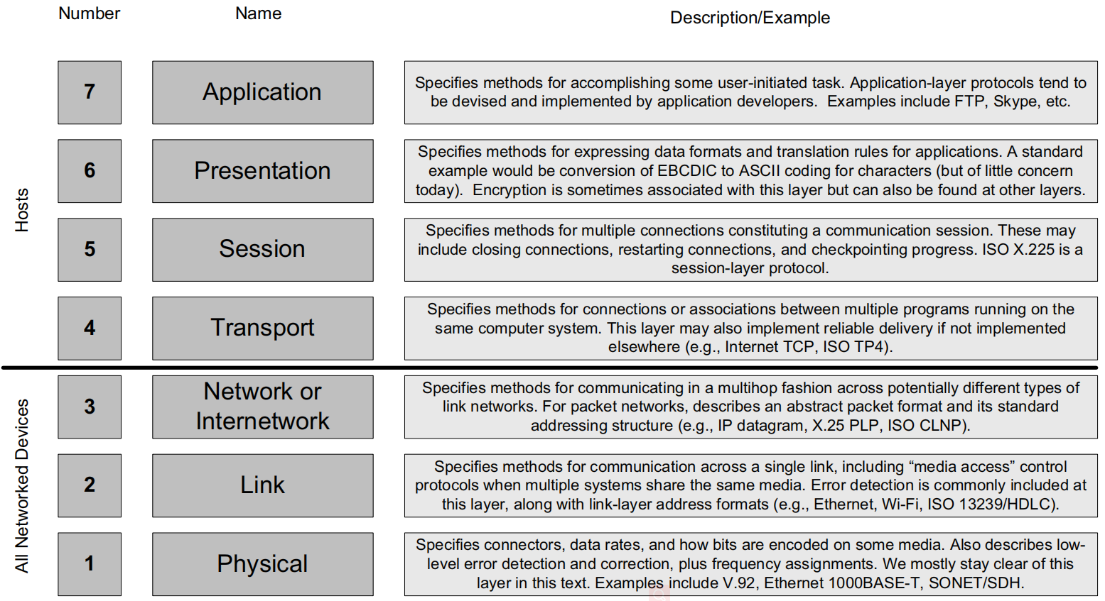
What we care about most is the network layer.
The Correspondence Between TCP/IP’s Four-Layer Network Model and the OSI Seven-Layer Network Model#
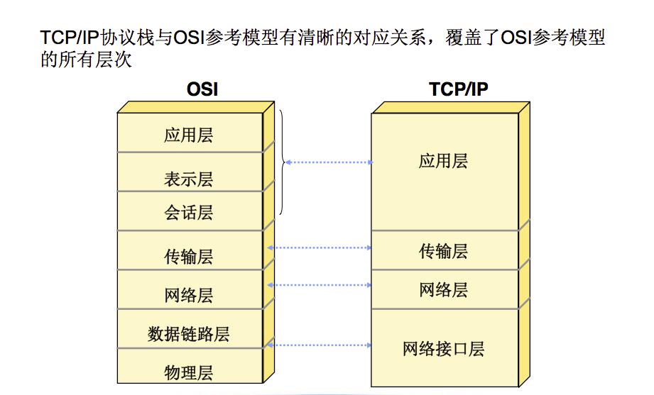
Multiplexing, Demultiplexing, and Encapsulation in a Layered Implementation#
Multiplexing#
Multiplexing allows multiple protocols to coexist in the same infrastructure, and also allows multiple instances of the same protocol object (such as a connection) to exist simultaneously without being confused.
Demultiplexing#
Protocol objects are encapsulated layer by layer. When the receiver wants to process the corresponding protocol, it needs to demultiplex the protocol object, generally handling it via the demultiplexing identifier in the corresponding layer’s PDU.
The demultiplexing identifier is generally a hardware address, an IP address, or a port number.
Encapsulation#
When an object (packet, message, etc.) of a PDU (protocol data unit) at one layer is carried by a lower layer, this process is called encapsulation in the adjacent lower layer. The essence of encapsulation is that each layer promises not to look at the data of the layer above it, treating the upper layer’s data as opaque information that needs no interpretation.
Multiplexing, Demultiplexing, and Encapsulation in TCP/IP#
Ethernet Frames#
An Ethernet frame contains MAC addresses and an Ethernet type field.
MAC Address
The MAC address, i.e. the Media Access Control address, is also called the link-layer address. It uniquely identifies a network card. 48 bits.
Ethernet Type Field
Used to select the network-layer protocol that processes the Ethernet frame. 16 bits. 0x0800 indicates that this frame contains an IPv4 datagram.
Payload#
The bytes other than the frame’s header and trailer make up the frame’s payload. The payload is the useful information data for the receiver.
Port Number#
A port number is a 16-bit non-negative integer (range 0~65535).
Well-known ports: 0~1023
Registered ports: 1024~49151
Dynamic/private ports: 49152~65535
Internet, Intranet, and Extranet#
Internet#
Lowercase “internet” refers to multiple networks interconnected using a common protocol suite.
Uppercase “Internet” refers to the worldwide collection of hosts that can communicate using TCP/IP. The Internet is an internet, but the reverse is not true.
Intranet#
This is what we call an internal network, a LAN, or a corporate/company internal network, implemented through firewalls.
Extranet#
When partners connect to a company’s intranet via VPN, this kind of VPN-involving network is called an extranet.
Designing Applications#
Client/Server Structure#
That is, the client/server structure: the network application is designed with a server on one end and a client on the other. The server provides some type of service to the client, such as accessing files on the server.
Servers fall into two categories: iterative and concurrent.
Iterative means blocking loop processing, which gives a very poor user experience and is rarely used nowadays.
Concurrent means an asynchronous server, usually implemented with multithreading/async functions/IOCP.
P2P Model, Peer-to-Peer Networks#
Some applications are designed in a more distributed form, with no dedicated server, such as Skype (a chat and calling application) and BitTorrent (commonly known as BT); such software is called a P2P application or peer-to-peer network. A concurrent P2P application receives an incoming request, determines whether it can respond to it, and if it can’t, forwards the request to other peers. A group of P2P applications together form an application network called an overlay network. Thunder is BT download software based on P2P; the reason P2P is faster than ordinary downloading is that you can download content that other users (peers) have already downloaded, rather than downloading from a file server. The more people have downloaded a file, the faster the download. This is the “all for one, one for all” design philosophy.
Network API#
Whether C/S or P2P, you need to express the required network operations and program them. This is usually done through a network application programming interface.
The commonly used network API is the Socket (Berkeley Socket).
Attacks Related to the Internet Architecture#
Spoofing#
A malicious user inserts any IP address into the source address field of each IP datagram they send.
DoS and DDoS Attacks#
A DoS attack, i.e. a denial-of-service attack, works by consuming a large amount of the server’s resources, causing traffic congestion so that legitimate users are denied service.
A DDoS attack, i.e. a distributed DoS attack, uses multiple computers to launch a DoS attack against a target machine.
Unauthorized Access#
That is, accessing information or resources in an unauthorized way. In network security, after breaking into a target machine you often lack administrator privileges, which leaves you in an unauthorized state, requiring privilege escalation or impersonating an administrator. Privilege escalation is often done by obtaining the administrator’s authentication information and thereby raising your user level. Impersonating an administrator is done by stealing the administrator’s user security credentials to disguise yourself as the administrator. This impersonation is a form of unauthorized access.
Summary#
The Difference Between the Network Layer and the Transport Layer#
- The network layer (IP) provides an unreliable datagram service, which must be implemented by all addressable systems in the Internet.
- The transport layer (TCP/UDP) provides end-to-end services for applications running on end hosts. TCP provides ordered, reliable stream delivery with flow control and congestion control mechanisms, commonly used for applications that generally need reliability guarantees, such as online games. UDP provides high-speed, unreliable transmission, commonly used for broadcast/multicast and for video transmission.
DNS#
DNS is actually a distributed database application running on the Internet.
IP Address Structure#
Representing IP Addresses#
IP addresses currently come in two kinds: IPv4 and IPv6.
IPv4 Addresses#
An IPv4 address is a 32-bit non-negative integer. For convenience, it’s represented in dotted-quad notation, with each group being 8 bits.
For example, 00000001000000100000001100000100 in dotted-quad notation becomes:
First split it into four groups: 00000001, 00000010, 00000011, 00000100
Then convert each group’s binary to decimal: 1, 2, 3, 4
Then separate each decimal group with a .: 1.2.3.4
IPv6 Addresses#
An IPv6 address is 4 times the length of an IPv4 address, i.e. 128 bits. For convenience, it’s represented using 8 blocks, each block being 4 hexadecimal digits. Blocks are separated by :.
Since IPv6 addresses are very long, there are naturally rules for abbreviation:
- Leading zeros must be compressed (for example,
2001:0db8::0022becomes2001:db8::22) ::can only be used where it has the greatest effect (compressing the most zeros), but it’s not limited to 16-bit blocks. If multiple blocks contain equal-length runs of zeros, the earlier block is replaced by::- The hexadecimal digits
athroughfshould be in lowercase
Basic IP Address Structure#
Unicast Addresses#
Most IPv4 addresses are ultimately subdivided into a single address that identifies a network interface of a computer connected to the Internet or to some private intranet. These addresses are called unicast addresses.
Classful Addressing#
The division of the address space involves five major classes: A, B, C, D, E, F.
Class A: 8-bit network number, with the first bit fixed at 0 and the other 7 bits free. 24-bit host number.
Class B: 16-bit network number, with the first two bits fixed at 10 and the other 14 bits free. 16-bit host number.
Class C: 24-bit network number, with the first 3 bits fixed at 110 and the other 21 bits free. 8-bit host number.
Class D: 32-bit multicast address, with the first four bits fixed at 1110 and the other 28 bits free.
Class E: reserved, with the first four bits being 1111 and the other 28 bits free.
Subnet Addressing#
That is, the host number is further divided into a subnet ID + a host ID.
For example, after setting the subnet mask 255.255.255.0 on the originally 16-bit host number of a Class B address, the host number is divided into an 8-bit subnet ID + an 8-bit host ID. This divides a site into 256 subnets, with each subnet containing at most 254 hosts (256-2, because the 0 and 255 addresses are invalid).
Subnet Mask#
A subnet mask is a set of assignment bits used by a host or router to determine how to obtain network and subnet information from a host’s corresponding IP address. It’s the same length as the IP address.
It can be configured statically (on a router) or dynamically (via DHCP, the Dynamic Host Configuration Protocol).
Performing a bitwise AND between the IP address and the subnet mask yields the network/subnet identifier (prefix) of the address used for routing.
For example, 128.32.1.14 with a mask of length 24, 255.255.255.0 (/24), after a bitwise AND, gives 128.32.1.0/24, i.e. the subnet identifier.
Routers outside the site make routing decisions based only on the network-number portion of the address; they don’t need the network/subnet or host portion.
Broadcast Address#
Each IPv4 subnet has a special address that serves as the subnet broadcast address.
Calculation Process#
The process for calculating the subnet broadcast address:
- Invert the subnet mask
- Perform a bitwise OR between the IP address and the inverted subnet mask
For example, for 128.32.1.14 with subnet mask 255.255.255.0, calculate the subnet broadcast address:
- Bitwise-invert
255.255.255.0to get0.0.0.255 - Perform a bitwise OR between
128.32.1.14and0.0.0.255to get128.32.1.255
So the subnet broadcast address of 128.32.1.0/24 is 128.32.1.255.
Directed Broadcast#
By sending an IP datagram whose destination address is the subnet broadcast address, a router then forwards it to all hosts in the subnet; this kind of broadcast is called a directed broadcast and is currently disabled for security reasons.
Local Network Broadcast#
Besides the subnet broadcast address, the special address 255.255.255.255 is reserved as the local network broadcast address; it isn’t forwarded by routers and is accomplished through the link layer’s broadcast mechanism.
Multicast Address#
An IP multicast address identifies a group of host interfaces.
Anycast Address#
An anycast address is a unicast address that points to different hosts depending on the sender’s location; this kind of address is often used to discover network services that may appear in different locations. (The most suitable, the closest.)
The Link Layer#
Half-Duplex and Full-Duplex#
Half-Duplex#
Half-duplex refers to a communication mode in which you can only send or only receive at any given time.
Full-Duplex#
Full-duplex refers to a communication mode in which you can both send and receive data at the same time.
Collision Detection#
CSMA#
CSMA, Carrier Sense Multiple Access, uses a first-come-first-served approach to occupy the channel and send data. If multiple stations send frames at the same time, a collision occurs, which causes network congestion and performance degradation.
CSMA/CD#
CSMA/CD, Carrier Sense Multiple Access with Collision Detection. How it works:
- If there’s no data flowing on the carrier channel, any station can send data.
- Check whether a collision will occur. Once a collision occurs, abandon sending the data and immediately release the carrier channel.
- After abandoning the transmission, wait a random delay and then contend for the medium again to retransmit the frame.
CSMA/CA#
CSMA/CA, Carrier Sense Multiple Access with Collision Avoidance. How it works:
- First detect whether the channel is in use. If the channel is detected to be idle, wait a random amount of time before sending the data.
- If the receiving end correctly receives the frame, then after an interval it sends an acknowledgment frame ACK to the sending end.
- When the sending end receives the ACK frame, confirming that the data was transmitted correctly, it waits another interval before sending data again.
WiFi commonly uses CSMA/CA, not CSMA/CD.
Ethernet Frames#
An Ethernet frame mainly contains two MAC addresses (destination address DST and source address SRC) and a payload.
MAC Address#
A MAC address is a 6-byte (48-bit) address and is the unique identifier of a network card.
Loop Detection#
Spanning Tree Protocol (STP)#
STP uses the spanning tree algorithm to solve the problem of redundant loop topologies.
Rapid Spanning Tree Protocol (RSTP)#
RSTP improves on STP’s algorithm and is faster and more efficient than STP.
Loopback#
The loopback mechanism enables a client to communicate with a server on the same computer. It looks like a real network interface, but it’s actually a dedicated virtual software provided by the operating system that can communicate with other parts of the same host via TCP/IP.
In IPv4, the loopback address is 127.0.0.1, with the name localhost.
MTU and Path MTU#
MTU#
There’s a limit on the frame size of a PDU; this characteristic is called the Maximum Transmission Unit (MTU). In IP, if a datagram exceeds the link-layer MTU, IP will “fragment” the datagram so that each fragment is smaller than the MTU.
Path MTU#
When two hosts communicate across multiple networks, each link may have a different-sized MTU. The smallest MTU over the entire network path containing all the links is called the path MTU.
Path MTU Discovery#
The path MTU discovery mechanism can find the path MTU and fragment according to it, thereby reducing the number of fragmentations and improving efficiency.
Tunneling#
Network A uses IPv6, network B uses IPv4, and network C uses IPv6, with network A connected to network C through network B; in this case you need to use an IP tunnel so that networks A and C can communicate normally.
The principle of tunneling is to prepend an IP header to the original datagram and then forward it.
ARP: Address Resolution Protocol#
Introduction to ARP#
Knowing only a host’s IP address isn’t enough, because the Ethernet driver needs to know the host’s hardware address (MAC address) in order to send data further.
For TCP/IP networks, the Address Resolution Protocol (ARP) provides a mapping between IPv4 addresses and the hardware addresses used by various network technologies.
ARP applies only to IPv4; IPv6 uses the Neighbor Discovery Protocol, which is incorporated into ICMP.
ARP provides a dynamic mapping from network-layer addresses to the associated hardware addresses. Dynamic means it’s performed automatically and changes over time without the system administrator having to reconfigure it.
The ARP Process#
The ARP workflow:
- Send an ARP request to all hosts in the broadcast domain: “If your IP is X.X.X.X, tell me your MAC address”
- Some host in the domain receives the ARP request and sends back a response to the requester: “Hello, my IP is X.X.X.X, and my MAC address is X:X:X:X:X:X”
- The host that received the request self-learns, recording the IP-to-MAC-address mapping in memory for later use (the ARP cache)
ARP Cache Timeout#
ARP generally re-runs after 20 minutes.
Proxy ARP#
Proxy ARP, also called promiscuous ARP or ARP hack, has the function of letting two physical networks hide themselves from each other. Some old devices that don’t support subnetting need to use proxy ARP.
Gratuitous ARP#
Gratuitous ARP refers to a host sending an ARP request looking for its own MAC address.
ARP-Related Attacks#
ARP disconnection attack: using proxy ARP to achieve ARP spoofing, it can generate a large amount of ARP traffic in the network to congest it. As long as the attacker keeps sending forged ARP response packets, they can change the IP-MAC entries in the target host’s ARP cache, causing a network outage or a man-in-the-middle attack.
The Internet Protocol#
Introduction to IP#
IP is the core protocol in the TCP/IP protocol suite. All TCP, UDP, ICMP, and other data is transmitted via IP datagrams.
IP provides a best-effort (it transmits IP datagrams as best it can, without guaranteeing that an IP datagram will successfully reach its destination), connectionless datagram delivery service.
IP’s error handling: discard some data. Any reliability must be provided by an upper layer (such as TCP).
Connectionless means IP doesn’t maintain any connection state information related to datagrams in network elements; each datagram is handled independently of the others. That is, IP datagrams may be delivered out of order, and a datagram sent earlier may be processed later.
IP Header#
The IPv4 header is generally 20 bytes. The IPv6 header is fixed at 40 bytes.
IPv4 Header Fields#
- Version number, 4 bits. 4 means IPv4, 6 means IPv6; there are other versions, but they’re rarely used.
- IHL, Internet Header Length (the number of 32-bit words (4 bytes)), 4 bits. This limits the IPv4 header length to at most 60 bytes (4*15).
- DS, DiffServ, the differentiated services field, 6 bits. Used to support different types of service on the Internet.
- ECN, the congestion identifier, 2 bits. A persistently congested, ECN-aware router sets these two bits when forwarding packets. Used to avoid or handle network congestion.
- Total length, 16 bits. Indicates the total length of the IPv4 datagram (in bytes). From IHL + total length you can determine where the datagram’s data portion starts and the length of the data portion.
- TODO
The Internet Checksum#
The Internet checksum is a 16-bit numeric sum used to detect whether a received message matches the one that was sent.
- First set the datagram’s checksum field value to 0
- Then compute the 16-bit one’s-complement sum over the header
- Store the one’s-complement sum in the checksum field
- If the checksum is 0, there’s no error in the header; otherwise an error has occurred in the header.
For a datagram with an error, IPv4 discards it rather than generating an error message. The higher layers detect the lost datagram in some way and resend it if necessary.
IP Forwarding#
If it’s a peer network or a shared network, an IP datagram can be sent directly to the destination without a router. Otherwise, the host sends the datagram to a router, which forwards and delivers the datagram to the destination.
TODO#
Firewalls and Network Address Translation#
Firewalls#
A firewall is a kind of router that can restrict the types of traffic it forwards.
Packet-Filtering Firewall#
A packet-filtering firewall is an Internet router that can discard packets that match (or don’t match) specific criteria.
Proxy Firewall#
A proxy firewall is a multihomed server host; it’s the endpoint associated with TCP and UDP transport and generally doesn’t route IP datagrams at the IP protocol layer.
Network Address Translation (NAT)#
NAT is essentially a mechanism that allows the same set of IP addresses to be reused in different places on the Internet. The motivation for establishing NAT is the rapidly dwindling, limited IP address space.
Problems NAT Solves#
The introduction of NAT solves two problems:
- IP address exhaustion
- Concerns about routing scalability
Disadvantages of NAT#
NAT’s disadvantages:
- It requires special configuration
- For NAT to work, every bidirectional packet belonging to the same connection or association must pass through the same NAT (because NAT must rewrite each packet’s addressing information so that systems in the private address space and Internet hosts can communicate normally)
- Modifying the IP-layer address also requires simultaneously modifying the transport-layer checksum
- It causes trouble for some application protocols, especially those that record IP address information in the application-layer payload (such as FTP)
How NAT Works#
NAT works by rewriting the identifying information of packets passing through the router. It needs to rewrite the source IP address of packets traveling in one direction, and rewrite the destination IP address of packets traveling in the other direction.
NAT and Packet Filtering#
Most NATs perform both translation and packet filtering, with the packet-filtering criteria depending on the NAT’s dynamic state.
Basic NAT and NAPT#
Basic NAT rewrites the IP address but keeps the port number unchanged.
NAPT (Network Address Port Translation), also called IP masquerading, usually maps all addresses to a single address. It sometimes has to rewrite port numbers to avoid conflicts.
NAT’s Common Policy#
It allows almost all outgoing traffic and its return traffic (corresponding to the outgoing traffic) to pass through the NAT, but blocks almost all incoming new connection requests. This behavior suppresses “probing” attacks that try to determine the IP addresses of exploitable live hosts.
NAT and TCP#
TODO
User Datagram Protocol (UDP) and IP Fragmentation#
UDP#
UDP is a simple, datagram-oriented transport-layer protocol that preserves message boundaries. It doesn’t provide error correction, queue management, duplicate elimination, flow control, or congestion control.
It does provide error detection, including an end-to-end checksum. It provides only minimal functionality, so an application using it has to do a lot of control work regarding how packets are sent and processed. To ensure data is delivered reliably or correctly ordered, the application must implement these protections itself.
Pros and Cons of UDP#
Cons:
- It provides no error correction and doesn’t guarantee that the data passed to the IP layer will reach its destination
- There’s no protocol mechanism to prevent high-speed UDP traffic from negatively affecting other network users
Pros:
- Lower overhead
- Well suited to implementing broadcast and multicast
- The application can choose its own retransmission unit
UDP Header#
- Source port number, 2 bytes
- Destination port number, 2 bytes
- Total length (the length of header + data), 2 bytes
- Checksum, 2 bytes
Here, the UDP checksum is computed based on the source port number, destination port number from the UDP header, and a pseudo-header. Any modification to a UDP header field requires correspondingly modifying the UDP checksum field.
The total length field is actually redundant, because the UDP/IPv4 datagram can be obtained by subtracting the IPv4 header length from the IPv4 datagram’s total length.
UDP Checksum#
The UDP checksum is an end-to-end transport-layer checksum. It covers the UDP header, the UDP data, and a pseudo-header. It’s computed by the sender and verified by the final destination. It isn’t modified in transit (unless it passes through a NAT).
The UDP checksum is optional.
Computing the UDP checksum is similar to computing an ordinary Internet checksum, but with two small details:
- A UDP datagram can be an odd number of bytes, so an odd-length UDP datagram has a padding (virtual) byte with a value of 0 appended to its tail. Virtual means it’s used only for the computation and isn’t transmitted.
- To verify correct arrival, when computing the checksum UDP includes a UDP pseudo-header, which contains the source and destination addresses from the IP header as well as the protocol or next-header field. It too is used only for the computation and isn’t transmitted.
Name Resolution and the Domain Name System (DNS)#
DNS#
DNS is a distributed C/S network database used by TCP/IP applications to map between host names and IP addresses.
A First Look at TCP#
Means of preventing information from being corrupted:
- Error-correcting codes, i.e. adding some redundant bits so that even if some bits are destroyed, the true information can be recovered.
- Automatic Repeat Request (ARQ). TCP uses this method for error correction.
ARQ and Retransmission#
An acknowledgment (ACK) refers to the receiver signaling the sender to confirm that it has received a packet.
The ACK pattern:
- The sender sends a packet and waits for an ACK.
- The receiver receives the packet and responds with an ACK.
- The sender receives that ACK and then sends another packet.
But this has several problems:
- How long should the sender wait for an ACK?
- What if the ACK is lost?
- What if the packet is received but contains an error?
The first problem involves policies related to the retransmission timeout.
For the second problem, using a resend policy may result in duplicate packets, so sequence numbers are needed to mark packets and solve the duplication problem; once a packet is duplicated, the duplicate is discarded.
The third problem is generally solved using a checksum.
Packet Windows and Sliding Windows#
Packet Window#
The packet window is the set of packets that have been injected by the sender but not yet acknowledged.
Window Size#
The number of packets in the packet window is called the window size.
The Sliding Window Protocol#
The sliding window protocol is a buffer-based optimization strategy.
Variable Windows: Flow Control and Congestion Control#
Flow Control#
Flow control means that when the receiver can’t keep up, it forces the sender to slow down.
Rate-Based Flow Control#
Rate-based flow control assigns the sender a certain rate and ensures that data can never be sent faster than that rate.
It’s suitable for applications, broadcast, multicast discovery, and so on.
Window-Based Flow Control#
Window advertisement / window update: with a sliding window, this lets the receiver tell the sender how large a window to use, so as to dynamically adjust (update) the window size.
Congestion Control#
The sender’s rate may exceed the capacity of some router, leading to packet loss. This can be handled with a form of flow control called congestion control.
Congestion control involves the sender slowing down so as not to overwhelm the network between it and the receiver.
Explicit Signaling#
Use window advertisements or other methods to explicitly tell the sender to slow down.
Implicit Signaling#
Guess whether slowing down is needed based on some other evidence.
Retransmission Timeout#
The Problem#
How large should the retransmission timeout be?
Intuitively, the retransmission timeout should be roughly: the time to send the packet + the time for the receiver to process it and send an ACK + the time for the ACK to return to the sender + the time for the sender to process the ACK.
Unfortunately, none of these times can be known exactly. Worse still, some or all of them can change at any time, decreasing as the extra load from end hosts or routers increases.
A Better Strategy — Estimation#
Through statistical analysis, take the mean of a set of RTT samples as an estimate of the RTT; this is called round-trip-time estimation.
The mean isn’t actually all that reasonable either, so there are still more problems, which TCP handles in practice.
The TCP Service Model#
TCP provides a connection-oriented, reliable, byte-stream service.
Connection-oriented means that two applications using TCP must contact each other to establish a TCP connection before they can exchange data.
TCP has no record markers or message boundaries.
TCP’s Reliability#
Packetization#
TCP provides a byte-stream interface, so TCP must convert a sending application’s byte stream into a set of packets that IP can carry. This is called packetization.
Packets contain sequence numbers; a sequence number isn’t a packet number but the byte offset of each packet’s first byte within the entire data stream.
Repacketization#
Packets are variable-sized in transmission and are allowed to be combined, which is called repacketization.
Segment#
The block TCP passes to IP is called a segment.
TCP Checksum#
TCP maintains a mandatory checksum. The TCP checksum covers the TCP header + the TCP data + the IP header.
A TCP segment with a checksum problem is discarded.
Retransmission Timer#
When TCP sends a group of segments, it usually sets a retransmission timer and waits for the other side to receive them.
Robustness of the ACK#
An ACK indicating byte number N implies that all bytes up to N (but not including N) have been successfully received.
Duplex Service#
TCP provides applications with a duplex service. Data can flow in both directions, and the two directions are independent of each other.
Sequence Numbers#
Sequence numbers let the TCP receiver conveniently discard duplicate segments and record segments that arrive in jumbled order.
TCP Header and Encapsulation#
The TCP header is between 20 and 60 bytes. A TCP header with no options is 20 bytes, and TCP headers usually don’t carry options.
- Source port, 16 bits
- Destination port, 16 bits
- Sequence number, 32 bits. Identifies a byte of the data stream from the TCP sender to the receiver; this byte represents the first byte (offset) in the data of the segment containing that sequence number.
- Acknowledgment number, 32 bits. Also called the ACK number or the ACK field, valid only when the ACK bit field is enabled. The value it contains is the next sequence number the sender of the acknowledgment expects to receive, i.e. the sequence number + 1.
- Header length, 4 bits. In units of 4 bytes, so the TCP header is at most (2^4 - 1) * 4 = 60 bytes.
- Padding zeros (reserved), 4 bits
- CWR, 1 bit. Congestion Window Reduced (the sender has lowered its sending rate).
- ECE, 1 bit. ECN-Echo (the sender received an earlier congestion notification).
- URG, 1 bit. Urgent (the urgent pointer field is valid).
- ACK, 1 bit. Acknowledgment (the acknowledgment number field is valid; it’s generally enabled after the connection is established).
- PSH, 1 bit. Push (the receiver should deliver this data to the application as soon as possible).
- RST, 1 bit. Reset the connection (connection cancellation, generally because of an error).
- SYN, 1 bit. When establishing a connection, the SYN bit field of the first segment sent from the client to the server is enabled. Such a segment is called a SYN segment.
- FIN, 1 bit. The sender of this segment has finished sending data to the other side.
- Window size, 16 bits. This limits the maximum window to 65535 bytes, thereby limiting TCP’s throughput.
- TCP checksum, 16 bits. Covers the TCP header, data, and IP header. It also computes a pseudo-header.
- Urgent pointer, 16 bits. Valid only when the URG bit field is set.
- Options, optional, up to 40 bytes. The most common option is the MSS option, i.e. the maximum segment size option.
Endpoint / Socket#
The combination of an IP address and a port is called an endpoint, also called a Socket, or a Berkeley Socket.
TCP Connection Management#
TCP is a connection-oriented unicast protocol. Before sending data, the two communicating parties must establish a connection between each other. TCP must detect and repair all data transmission problems arising at the IP layer, such as packet loss, duplication, and errors.
During connection establishment, the two communicating parties need to exchange some options, which are considered the connection’s parameters. Options are at most 40 bytes.
Establishing and Terminating a TCP Connection#
TCP Connection#
A TCP connection is uniquely identified by a pair of sockets (a four-tuple consisting of the client IP, client port number, server IP, and server port number).
The Three Steps of a TCP Connection#
A TCP connection is usually divided into 3 phases: startup, data transfer (the connection is established), and exit (closing).
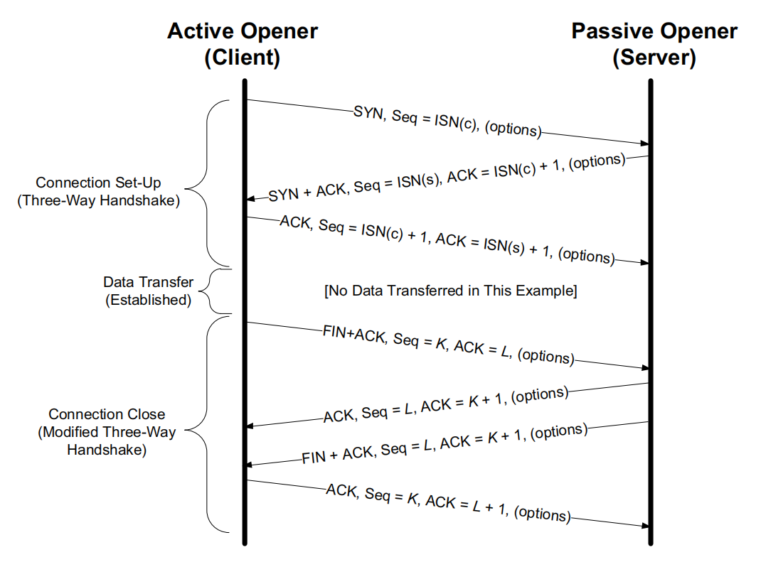
A TCP connection is established by calling connect; this process is called the three-way handshake.
A TCP connection is closed by calling close; this process is called the four-way handshake (four-way wave).
Q: Why is a four-way handshake needed?
A: Because TCP is full-duplex and supports half-close, the closing operation needs to be performed separately in each direction.
TCP Half-Close#
Closing a TCP connection by calling shutdown (rather than close) performs a TCP half-close operation.
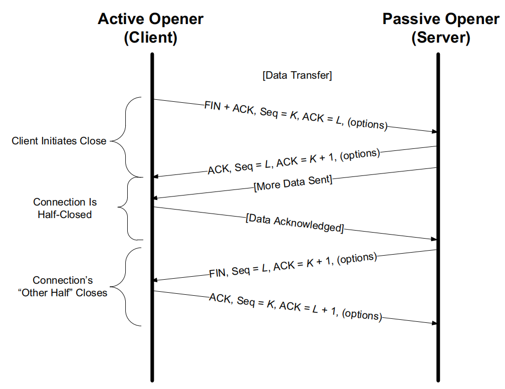
The side of a TCP connection that sends the FIN segment enters the half-close state after receiving the ACK segment; it will no longer send data but can continue to receive data until the other side sends a FIN segment.
Only when both sides have performed the half-close operation by calling shutdown is the entire connection fully closed.
Simultaneous Open and Simultaneous Close#
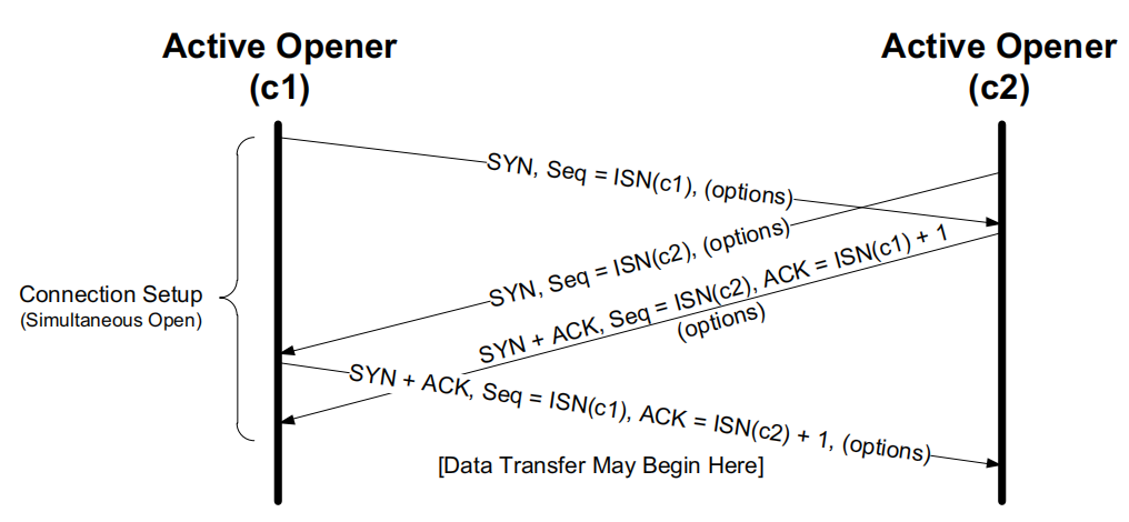
A simultaneous open requires four segments (SYN*2, SYN+ACK*2), one more segment than the three-way handshake.
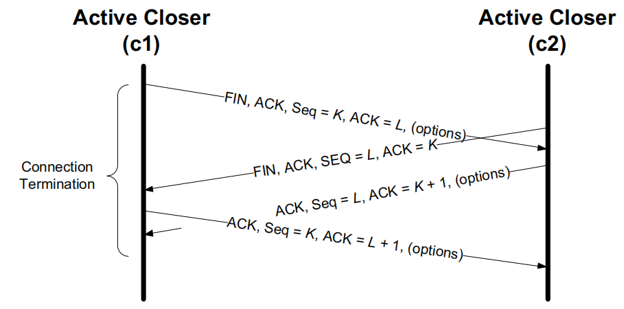
A simultaneous close requires four segments, the same as the four-way handshake, but the difference lies in whether the segment sequence is crossed or sequential: a simultaneous close is crossed, while the four-way handshake is sequential.
TCP Options#
A TCP segment is allowed to contain up to 40 bytes of options.
Maximum Segment Size Option#
The Maximum Segment Size (MSS) is the largest segment that the TCP protocol allows to be received from the other side.
The maximum segment size only counts the number of bytes of TCP data; it doesn’t include the other associated TCP and IP headers.
When establishing a TCP connection, each communicating party states its own allowed maximum segment size in the MSS option of its SYN segment.
The default maximum segment size value is 536 bytes. The typical IPv4 maximum segment size value is 1460 bytes.
Selective Acknowledgment Option#
By receiving the “SACK-permitted” option in a SYN (or SYN+ACK) segment, a TCP communicating party learns that it is capable of issuing SACK information.
Window Scale Option#
The window scale option (WSCALE or WSOPT) can effectively increase the range of the TCP window advertisement field from 16 bits to 30 bits.
Timestamp Option and Protection Against Wrapped Sequence Numbers#
Timestamp Option#
The timestamp option (denoted TSOPT or TSopt) requires the sender to add two 4-byte timestamp values to each segment. The sender fills a 32-bit (4-byte) value into the timestamp value field (called TSV or TSval) as the first part of the timestamp option. The receiver reflects these values in its acknowledgment, allowing the sender to estimate the TCP connection’s round-trip time for each ACK received. The receiver fills the received timestamp value into the timestamp echo reply field (called TSER or TSecr) as the second part of the timestamp option. When the timestamp option is included, the TCP header grows by 10 bytes (8 bytes to hold the two timestamp values, plus 2 bytes to indicate the option’s kind and length).
The timestamp option gives us more round-trip-time samples, thereby improving our ability to accurately estimate the round-trip time, which is more conducive to handling retransmission timeouts.
Protection Against Wrapped Sequence Numbers#
Since the sequence number is a 32-bit field, it wraps after exceeding its maximum value.
The Protection Against Wrapped Sequence numbers (PAWS) algorithm discards reappearing, already-discarded segments.
User Timeout Option#
The User Timeout (UTO) option is a relatively new TCP feature. The user timeout value (also called USER_TIMEOUT) indicates how long a TCP sender is willing to wait for an ACK confirming receipt of data before concluding that the other side failed to successfully receive the data.
Authentication Option#
The TCP Authentication Option (TCP-AO) uses a cryptographic hash algorithm and a secret value jointly maintained by the two parties of a TCP connection to authenticate each segment.
TCP Path Maximum Transmission Unit Discovery#
Packet Too Big#
You can use the IPv6 term “Packet Too Big” (PTB) to represent an ICMPv4 address-unreachable (fragmentation needed) or ICMPv6 Packet Too Big message.
The General Process#
When the connection is established, TCP uses the minimum of the outgoing interface’s MTU, or selects the sender’s maximum segment size (SMSS) based on the maximum segment size declared by the communicating peer.
Once the sender’s maximum segment size has its initial value selected, all IPv4 datagrams TCP sends over this connection will have the DF bit field set.
If a PTB message is received, TCP reduces the segment size and then retransmits with the modified segment size.
If the PTB message already contains the next-hop recommended MTU, the segment size value can be set to the next-hop MTU value minus the size of the IPv4 (or IPv6) and TCP headers.
If the next-hop MTU value isn’t present, the discoverer needs to try multiple values (binary search), which affects congestion control.
Since routes change dynamically, after reducing the segment size value for a while you need to try a larger value. The retry interval is generally 10 minutes.
TCP State Transitions#
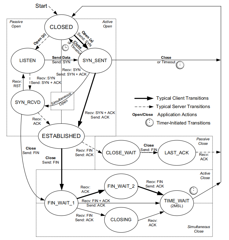
TCP State Transition Diagram#
TIME_WAIT State#
The TIME_WAIT state is also called the 2MSL wait state. In this state, TCP waits for twice the Maximum Segment Lifetime (MSL); it’s also called the doubled wait.
When TCP performs an active close and sends the final ACK, the connection must be in the TIME_WAIT state for twice the maximum lifetime. This lets TCP resend the final ACK to avoid a loss situation.
TCP always retransmits the FIN until it receives a final ACK.
Constraints of 2MSL#
While TCP is in the TIME_WAIT state, both communicating parties define the connection as unreusable, and any segments that arrive late are discarded.
If a port number is being used by any communicating end in the 2MSL wait state, that port number can’t be used again.
Client Active Close#
If the client performs an active close and then immediately restarts the same client, the new client also can’t reuse the same local port number. But this isn’t a big deal, because the client’s port number is an ephemeral port number assigned by the operating system.
Server Active Close#
If the server performs an active close and then immediately restarts the same server, the new server can’t reuse the same local port number; if it tries to start, it will report that the port is in use. Because the previous connection is in 2MSL, the port number is still part of the connection, and the connection is defined as unreusable, so the new server can’t start normally until 2MSL ends.
Quiet Time#
After a crash or restart, the TCP protocol should wait for a period equal to one MSL before creating new connections; this period is called the quiet time.
However, very few implementations do this; the vast majority of hosts take more than one MSL to restart after a crash or reboot.
FIN_WAIT_2 State#
When one communicating party actively closes, it sends a FIN to the other party; after receiving the ACK sent back by the other party, the active closer enters the FIN_WAIT_2 state.
Normally, only when the active closer receives the other party’s FIN will it enter the TIME_WAIT state; otherwise it would wait indefinitely.
However, Linux provides a timer: when the party in the FIN_WAIT_2 state has waited for the other side’s FIN longer than some threshold, and the connection is idle at that point, it will transition to the CLOSED state.
Transitions for Simultaneous Open and Close#
Simultaneous open: SYN_SENT -> SYN_RCVD
Simultaneous close: FIN_WAIT_1 -> CLOSING -> TIME_WAIT
Reset Segments#
Generally speaking, when TCP finds that an arriving segment is incorrect for the associated connection, it sends a reset segment.
Connection Request to a Nonexistent Port#
When a connection request arrives locally but there’s no associated process listening on the destination port, a reset segment is generated.
UDP handles this with an ICMP destination-unreachable message. TCP handles it with a reset segment.
Terminating a Connection#
At any time you can send a reset segment in place of a FIN to terminate a connection; this approach is sometimes called an abortive release.
- Any queued data is discarded, and a reset segment is sent out immediately (whereas a FIN is sent only after all queued data has been sent)
- The receiver of the reset segment knows that the other end used an abort rather than a normal close.
The receiver terminates the connection and notifies the application that the current connection has been reset. This usually causes a “connection reset by peer” error message or something similar.
Half-Open Connections#
As long as you don’t try to send data over a half-open connection, a properly functioning end won’t detect that the other end has crashed.
A half-open connection generally happens when a host’s power is suddenly cut (or the network cable is suddenly unplugged, or the cable is broken, haha; in short, it’s a passive disconnection of the Ethernet connection rather than actively closing TCP), rather than a normal shutdown.
A host (server) suddenly crashes, and at that point the client enters the half-open state; as long as the client doesn’t send data, it won’t know the server has crashed. If you then restart the server and the client sends data, the server knows nothing about the received data; it doesn’t remember anything about the previous connection, and it (the server) will reply with a reset segment, making the client close the connection (as if it said to the client, “Who are you? Have we met? Nothing you say matters, bye!”).
When simulating this, before restarting the server, disconnecting the Ethernet is to prevent it from sending a FIN over the already-open connection, because sending a FIN would mean the server is actively closing, in which case the client would respond with ACK and FIN, the server would reply with ACK, and both sides would close, which isn’t what we want.
Time-Wait Assassination#
During TIME_WAIT, if TCP receives some segments from the current connection, or more specifically a reset segment, the state can be destroyed; this is called Time-Wait Assassination (TWA).
A reset segment can “assassinate” the TIME_WAIT state and force the connection to close early. There are many methods to prevent this problem, including making the TIME_WAIT state ignore reset segments.
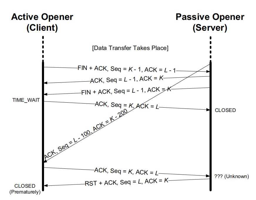
As shown in the figure, the client closes normally and enters the TIME_WAIT state, while the server enters the CLOSED state. If at this point a very old packet has just arrived at the client, the client will send an ACK segment with the latest sequence number and ACK number to the server. But this connection is already closed as far as the server is concerned; it knows nothing about this ACK segment and has no information about this connection, so it will reply with a reset segment to the client. After receiving this reset segment, the client will close and enter the CLOSED state. The client should have waited 2MSL before entering CLOSED, but it’s closed prematurely.
Many systems stipulate that no response is made to reset segments while in the TIME_WAIT state, thereby avoiding this problem.
TCP Server Options#
TCP servers are mostly concurrent: when a new connection request arrives at the server, the server accepts the connection and invokes a new process or thread (or IOCP, etc.) to handle the new client.
How a TCP server uses port numbers and how it handles multiple concurrent clients are crucial.
TCP Port Numbers#
TCP demultiplexes received segments based on the four-tuple. The destination IP address and destination port number, the source IP address and source port number—these four together form the local and remote nodes.
TCP can’t decide which process should get a received segment based on the destination port number alone. A node in the ESTABLISHED state can’t receive SYN segments, and a node in the LISTEN state can’t receive data segments.
Restricting the Local IP Address#
After the server restricts the local IP address, the client can only connect if it sets the destination address to the server’s local IP address. If the destination address isn’t the server’s local IP address, TCP will refuse the connection request and return a reset segment. The application won’t be aware of this request.
Restricting the Foreign Node#
local_IP must be a unicast IP address that applies to the local system.
If the server binds a port number using an IPv6 address, then that port number is also applied to the IPv4 address.
Entering the Connection Queue#
Two different connection queues handle two different states:
- Connections that aren’t yet complete but have received a SYN (in the SYN_RCVD state)—the half-connection queue
- Connections that have completed the three-way handshake and are in the ESTABLISHED state but haven’t yet been accepted by the application—the full-connection queue
Rules:
- When a connection request (SYN segment) arrives, the system-wide parameter
net.ipv4.tcp_max_syn_backlog(default 1000) is checked. If the number of connections in the SYN_RCVD state exceeds this threshold, the incoming connection will be rejected. - Each node in the listening state has a fixed-length connection queue. The connections in it have been fully accepted by TCP (the three-way handshake is complete) but not yet accepted by the application. The application imposes a limit on this queue, usually called the backlog. The backlog value must be between 0 and a system-specified maximum (
net.core.somaxconn, default 128). - If there’s still room in the listening node’s queue to allocate for a new connection, the TCP module will respond to the SYN and complete the connection. The application associated with the listening node won’t know about the new connection until the three-way handshake is complete. When the client’s active open operation completes successfully, the client may think the server is ready to receive data, yet the application on the server may not have been notified of the new connection at that point. If this happens, the server’s TCP module will queue the incoming data.
- If there’s no longer enough room in the queue to allocate for a new connection, TCP will delay responding to the SYN, giving the application a chance to catch up.
TCP Timeout and Retransmission#
When a data segment or acknowledgment is lost, TCP starts a retransmission operation to retransmit the unacknowledged data.
TCP has two independent mechanisms to accomplish retransmission: one is time-based, and the other is based on the composition of acknowledgment information. The second is more efficient.
Retransmission Timeout (RTO)#
When sending data, TCP sets a timer; if the acknowledgment for the data still hasn’t been received by the time the timer expires, it triggers the corresponding timeout or timer-based retransmission operation. The timer expiring is called the retransmission timeout (RTO).
Each retransmission interval is doubled, which is called binary exponential backoff.
TCP has two thresholds that determine how to retransmit the same segment: R1 and R2.
R1 indicates the number of retransmissions (or wait time) TCP is willing to attempt before passing a “negative advice” to the IP layer.
R2 (greater than R1) indicates when TCP should give up on the current connection.
R1 and R2 are set to at least 3 retransmissions and 100 seconds, respectively.
The R2 for a SYN segment is set to at least 3 minutes
R1 and R2 are configurable.
Configuration in Linux#
R1 is set via the system configuration variable net.ipv4.tcp_retries1, and R2 via the system configuration variable net.ipv4.tcp_retries2. The variable values are numbers of retransmissions, not units of time.
net.ipv4.tcp_retries1 defaults to 3. net.ipv4.tcp_retries2 defaults to 15, corresponding to 13~30 minutes.
For SYN segments,
net.ipv4.tcp_syn_retriesandnet.ipv4.tcp_synack_retriesdefault to 5, limiting the number of retransmissions.
Configuration in Windows#
R2 is set via the TcpMaxDataRetransmissions variable in the configuration registry HKLM\System\CurrentControlSet\Services\Tcpip\Parameters, corresponding to net.ipv4.tcp_retries2 in Linux. The default value is 5.
Timer-Based Retransmission#
Once the TCP sender has obtained a time-varying RTT measurement, it can set the RTO accordingly, and should ensure the retransmission timer is set reasonably when sending a segment.
Each TCP connection’s sender constantly sets and cancels a retransmission timer; if no data is lost, no timer expiration occurs.
If TCP doesn’t receive the ACK for the timed segment within the connection’s set RTO, a timeout retransmission is triggered. It responds quickly to this by reducing the current data sending rate.
There are two ways to accomplish this:
- Based on the congestion control mechanism, reduce the send window size
- Each time a retransmitted segment is retransmitted again, increase the RTO backoff factor (γ): RTO = γRTO. Usually γ=1, and as retransmissions mount, γ gradually doubles: 2, 4, 8, 16, …, but it generally doesn’t exceed the maximum backoff factor value (TCP_RTO_MAX in Linux, default 120s); once the corresponding ACK is received, γ is reset to 1.
Fast Retransmit#
The fast retransmit mechanism triggers retransmission based on feedback from the receiver (the receiver tells the sender about out-of-order packets) rather than a retransmission timer expiration.
Duplicate ACKs#
When an out-of-order segment is received, TCP must immediately generate an acknowledgment, i.e. a duplicate ACK, and the out-of-order situation indicates that a segment was lost before the subsequent data arrived, i.e. there’s a gap in the receiver’s buffer. The sender’s job is to fill this gap as quickly and efficiently as possible.
Duplicate ACK Threshold: dupthresh#
dupthresh is the threshold for duplicate ACKs, with a default of 3.
Overview of the Specific Algorithm#
After observing at least dupthresh duplicate ACKs, the TCP sender immediately retransmits the possibly lost data packet without waiting for the retransmission timer to expire.
Without SACK, at most one segment can be retransmitted before a valid ACK is received.
With SACK, an ACK can contain additional information, allowing the sender to fill multiple gaps within each RTT.
Retransmission with Selective Acknowledgment#
Principle#
The TCP receiver can provide the SACK feature, using the TCP header’s cumulative ACK number field to describe the data it has received.
Gap#
The interval between the ACK number and other data in the receiver’s buffer is called a gap.
Out-of-Order Data#
Data with a sequence number higher than the gap is called out-of-order data.
SACK Option#
A SACK option specifying n blocks is 8n + 2 bytes long, but since SACK is usually used together with the TSOPT option, which takes 10 bytes, SACK can only contain 3 blocks in each ACK.
Each block contains two parts:
- Left Edge of Block, 4 bytes, representing the starting sequence number of the out-of-order data stored by the receiver
- Right Edge of Block, 4 bytes, representing the last sequence number + 1 of the out-of-order data stored by the receiver
Receiver Behavior#
Receiving the SACK-permitted option during TCP establishment is enough for the receiver to generate SACKs. Generally speaking, whenever out-of-order data exists in the buffer, the receiver can generate a SACK.
Sender Behavior#
When a SACK sender performs a retransmission, usually because it received a SACK or a duplicate ACK, it can choose to send new data or retransmit old data. The SACK information provides the sequence-number ranges of the receiver’s data, so the sender can infer which gap data needs to be retransmitted. The simplest approach is to have the sender first fill the receiver’s gaps and then continue sending new data.
Packet Reordering and Packet Duplication#
We hope TCP can distinguish between reordering or duplication and loss.
Reordering#
The reordering problem can exist in the forward or reverse link of a TCP connection.
If it happens on the reverse (ACK) link, it causes the TCP sender’s window to advance rapidly, and then it may receive some obviously duplicate ACKs that should be discarded. Because of TCP’s congestion control behavior, this situation causes the sender to exhibit unnecessary traffic bursts (momentary high-speed sending), affecting the available network bandwidth.
If it happens on the forward link, TCP may be unable to correctly distinguish reordering from packet loss. When serious reordering occurs, TCP mistakenly thinks data has been lost, causing spurious retransmissions, mainly from the fast retransmit algorithm. Any out-of-order packet generates a duplicate ACK; to solve the problem of a large number of unnecessary retransmissions, fast retransmit is only triggered after the duplicate threshold (dupthresh) is reached.
Duplication#
The IP protocol can also transmit a single packet multiple times, which results in duplicate packets.
3 duplicate packets cause a spurious retransmission (fast retransmit). Using SACK (especially DSACK) you can simply ignore this problem.
With DSACK, each duplicate ACK contains information that the segment was successfully received, and doesn’t contain out-of-order data information.
Attacks Related to TCP Retransmission#
Low-rate DoS attack: the attacker sends a large amount of data to a gateway or host, keeping the victim system continuously in the retransmission-timeout state.
TCP Data Flow and Window Management#
Interactive Communication#
Communication such as ssh or online games is interactive communication; each transmitted data segment is relatively small, generally just a few dozen bytes.
For ssh, TCP handles both the data byte acknowledgment and the byte echo at the same time.
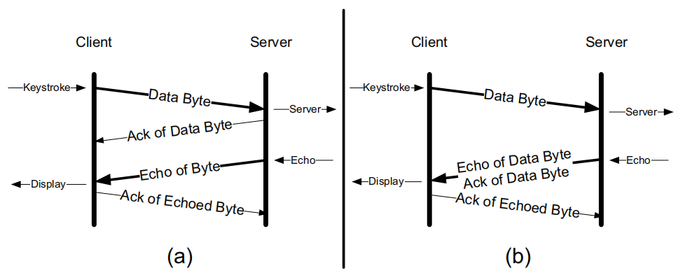
Every packet with data (length not 0) has PSH set. This flag usually indicates that the sender’s buffer is empty. That is, after a packet with PSH set has been sent, the sender has no other packets to transmit.
Delayed Acknowledgment#
Delayed acknowledgment can be implemented using TCP’s cumulative ACK field. Cumulative acknowledgment allows TCP to delay sending an ACK for a while, so the ACK can be combined with data that needs to be sent in the same direction; this is called piggybacking and is often used in bulk data transfer.
The Nagle Algorithm#
When a TCP connection has in-flight data (data that has been sent but not yet acknowledged), a small segment (with length less than SMSS) can’t be sent until all the in-flight data has been ACKed. And after receiving the ACK, TCP needs to gather these small pieces of data and combine them into one segment to send.
It implements self-clocking control: the faster the ACKs return, the faster the data is transmitted.
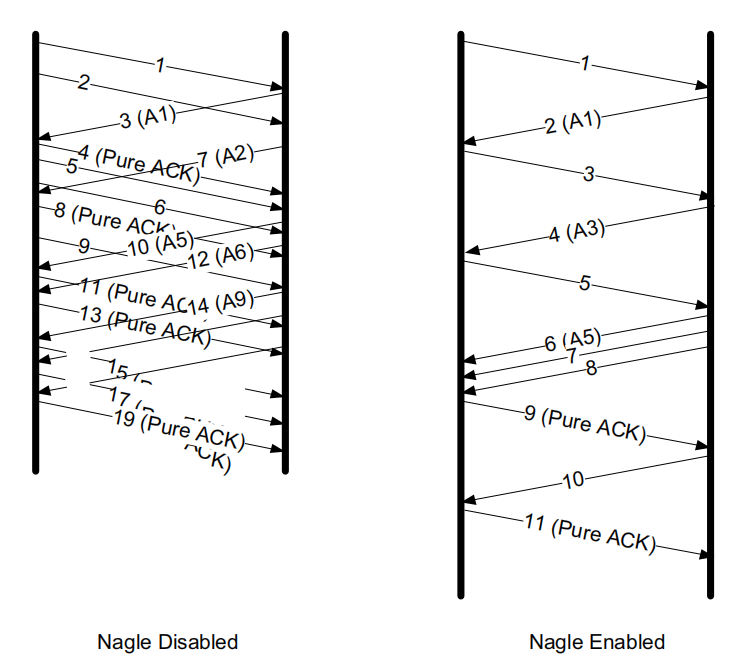
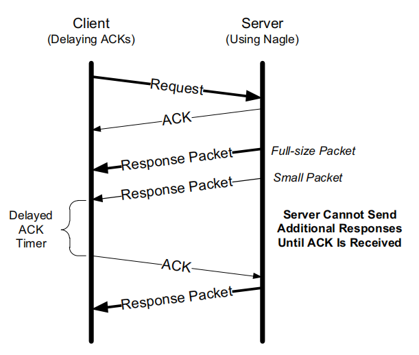
Combining Delayed ACK with the Nagle Algorithm#
If you combine delayed ACK with the Nagle algorithm directly, the result may be unsatisfactory, because a brief deadlock may occur that persists until the delayed-ACK timer expires.
Disabling the Nagle Algorithm#
The Socket API generally provides a method to disable it.
In Windows you can set the registry key HKLM\SOFTWARE\Microsoft\MSMQ\Parameters\TCPNoDelay
Setting it to 1 disables the Nagle algorithm.
Comments